Mesh to Point Cloud Step
Overview
The Mesh to Point Cloud step is an interactive plugin for the MAP-Client.
This plugin takes a Zinc compatible mesh EXF file as an input, and provides an interactive GUI allowing the user to create a point cloud by sampling the surface of the mesh. The Mesh to Point Cloud step outputs a new Zinc EXF file defining the sampled data points.
Specification
Information on this plugin’s specifications is available here.
Configuration
Information on this plugin’s configuration is available here.
Workflow Setup
Information on setting up a workflow with this plugin can be found here.
Instructions
When the plugin loads for the first time you should see something like the image displayed in Fig. 50. That is, you should see lines of your mesh displayed with yellow lines and white spheres depicting the nodes in the mesh.
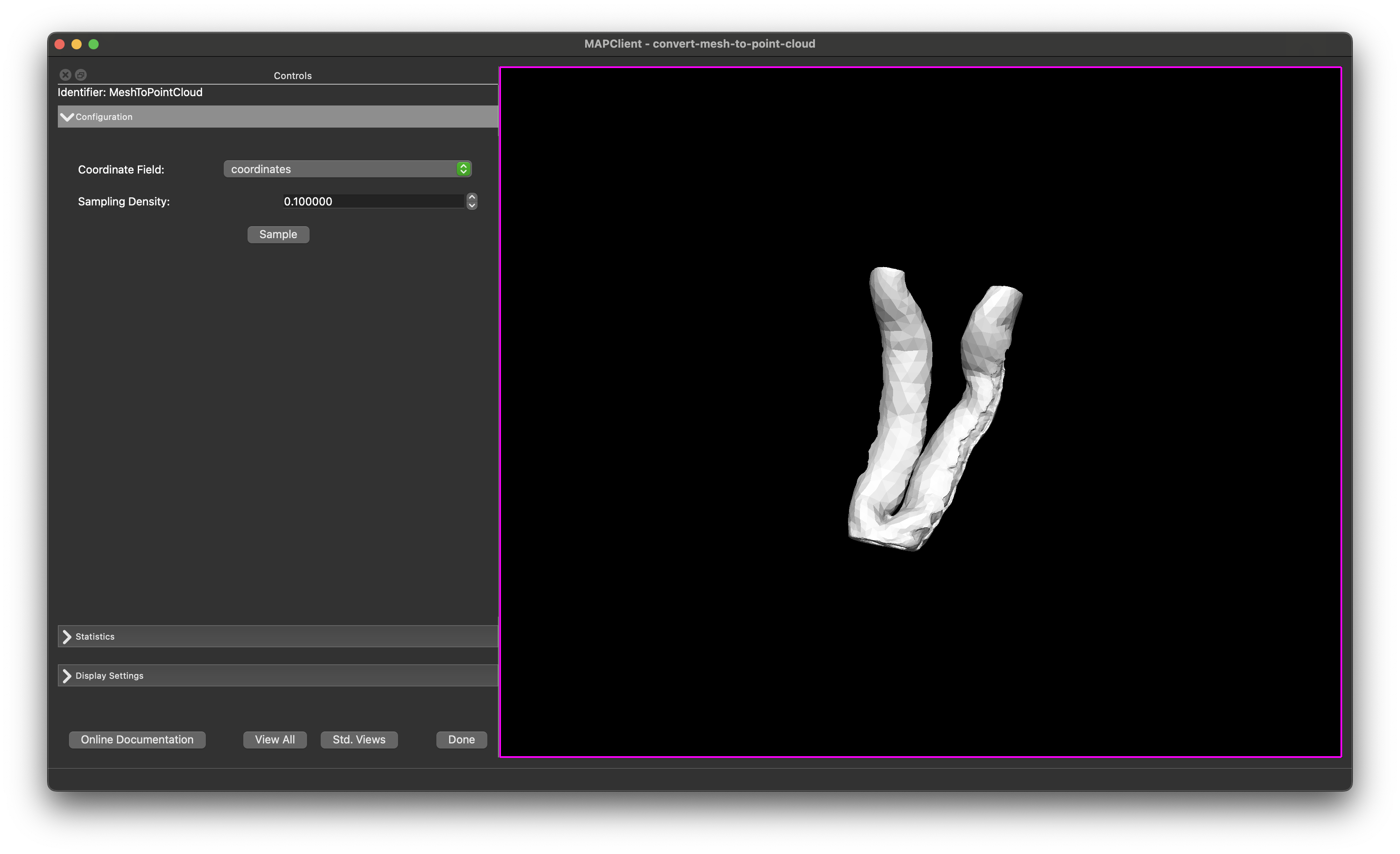
Fig. 50 Mesh to Point Cloud user interface in its initial state.
Graphics Coordinates
The coordinate fields used for the mesh is determined automatically, but can be changed using the combo-boxes in the Configuration section if required.
Display Settings
There are a number of check-boxes in the Display Settings section of the user interface (UI). Initially, only the Surface is enabled (as long as a mesh was successfully loaded from the EXF input) - as this is the only graphics that have been created at this point.
The size of the data-points can be adjusted with the Node Size spin box. If the points appear too small or if they aren’t initially visible, try increasing this value.
View
The View All button will reset the view of the mesh so that the whole mesh is visible within the scene. The Std. View button will reset the view to the next nearest standard view, continually clicking the `Std. View`button will cycle through the standard views.
General
The Done button will finish the step and continue with the workflow execution.
Usage
The Mesh to Point Cloud step allows the user to sample the surface of a mesh and create a point cloud. In the Configuration section, the user can set the density of points to generate over the surface of the mesh. The Point Density spin box allows the user to specify how many points to generate per unit square of surface area. The Statistics section displays the extent of the mesh, so you can use this to estimate a starting point for the point density setting.
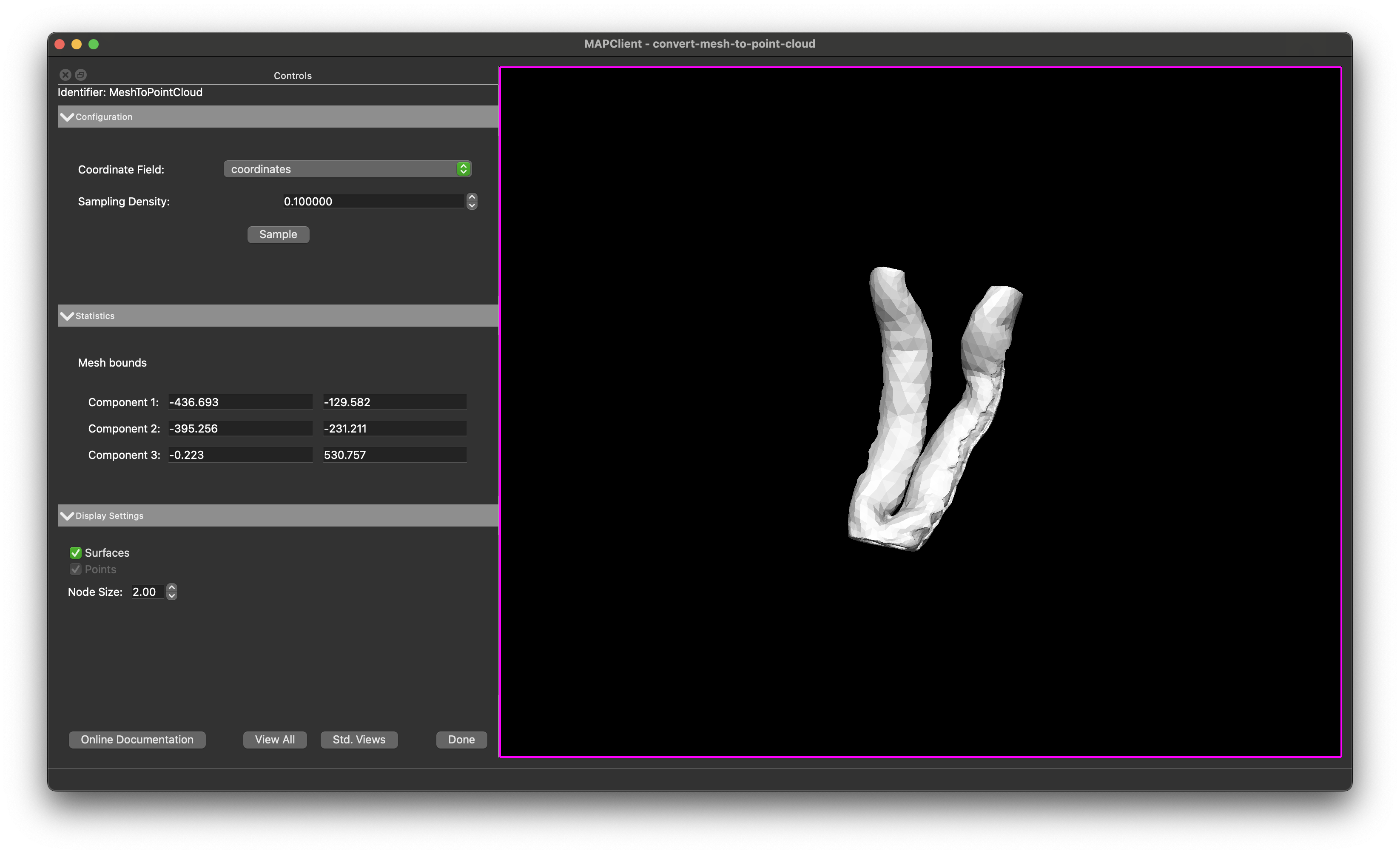
Fig. 51 Mesh to Point Cloud showing the configuration panel, statistics panel, and display settings panel.
Clicking the Sample button will sample the surface of the mesh and create a point cloud. The points will be displayed in the scene as blue spheres.
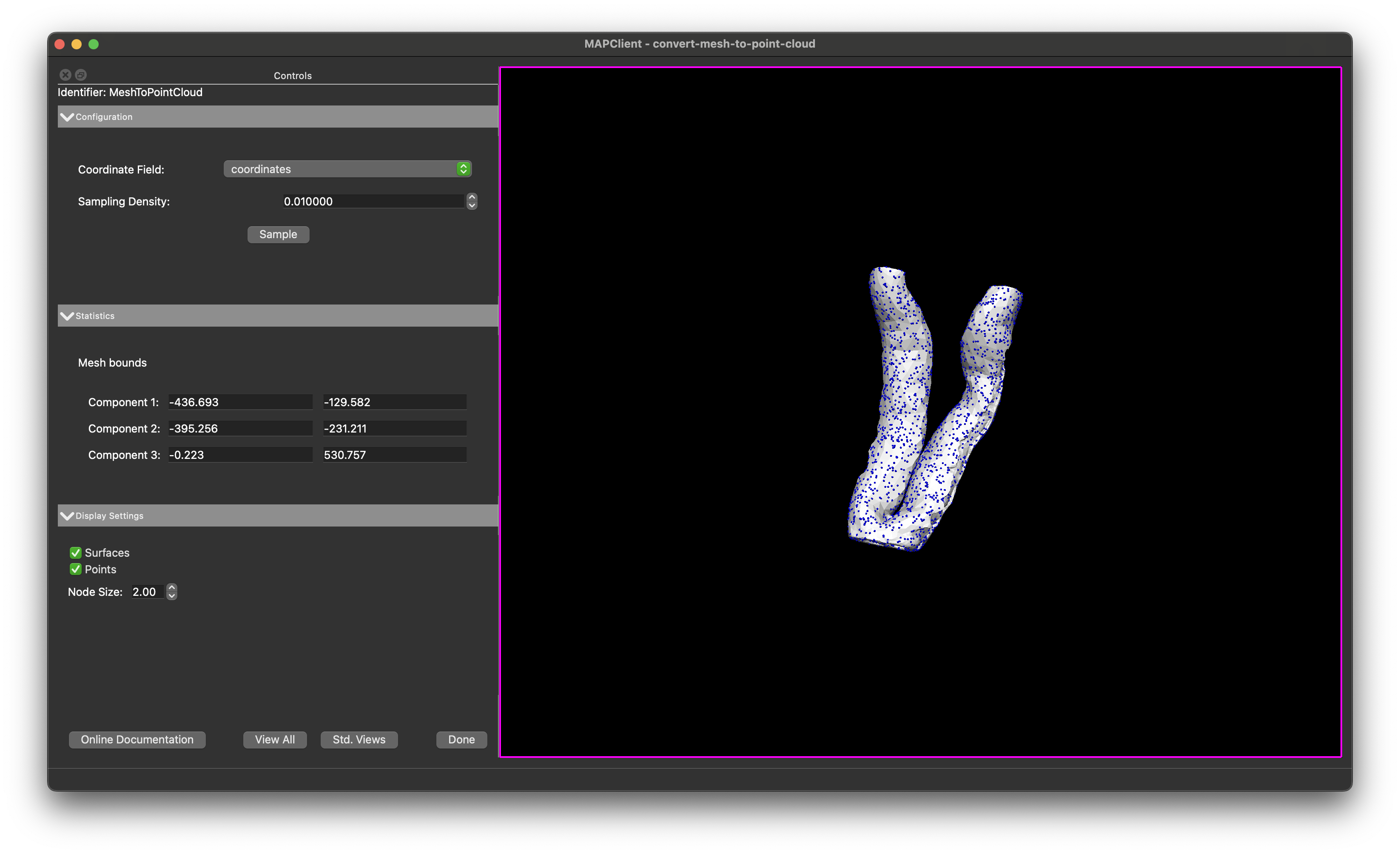
Fig. 52 Mesh to Point Cloud showing the result of clicking the Sample button.
The Sample button will only sample the surface of the mesh once, so if you want to change the point density or other settings, you will need to click the Sample button again after making changes.
Finishing
Clicking the Done button will output the data points to a Zinc EXF file and will execute any additional workflow steps connected to the Mesh to Point Cloud step.