Uterus Scaffold
The current uterus scaffold is 3D Uterus 1 built from class MeshType_3d_uterus1.
The human variant is shown in Fig. 131.
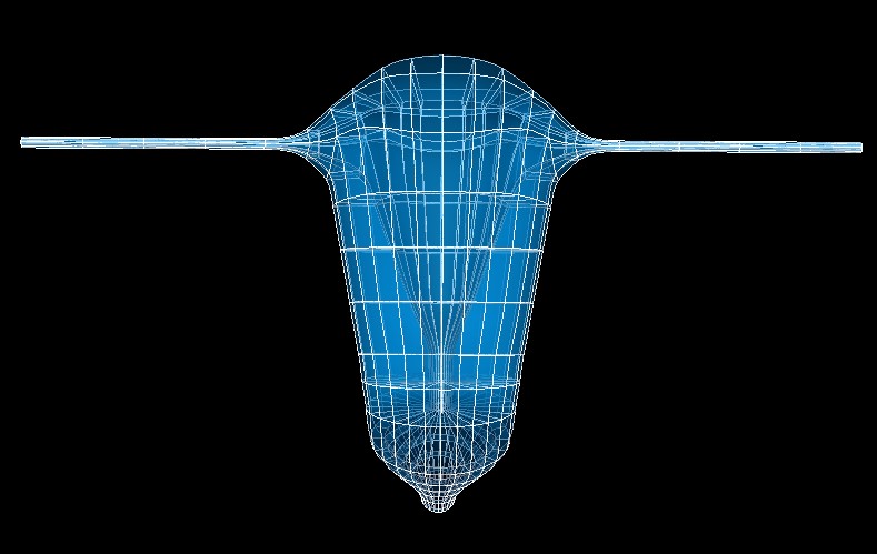
Fig. 131 Human uterus scaffold.
The uterus scaffold is a 3-D volumetric model of the uterus representing the oviducts, fundus, body, cervix, and vagina.
Variants
The uterus scaffold is provided with parameter sets for the following three species, which differ in shape:
Human
Mouse
Rat
These variants’ geometry and annotations are best viewed in the Scaffold Creator tool in the ABI Mapping Tools.
The uterus scaffold script generates the scaffold mesh and geometry from an idealization of their shapes. The mesh is derived from a one dimensional network layout with side axes controlling its lateral dimensions. The parameters were carefully tuned for each species, and it is not recommended that these be edited.
Instructions for editing the network layout are given with the ABI Mapping Tools Scaffold Creator documentation. Note that the D2 and D3 derivatives control the side dimensions, and derivatives D12 and D13 control the rate of change of these along the network layout. If editing, use the Interactive Functions to Smooth derivatives, Make side derivatives normal and Smooth side cross derivatives to make these as smooth as required.
The human, mouse, and rat uterus scaffolds are parameterized with literature data to represent the anatomy accurately.
Coordinates
The uterus scaffold defines the geometric coordinates.
The geometric coordinates field gives an approximate, idealized representation of the uterus shape for the species,
which is intended to be fitted to actual data for a specimen.
The uterus scaffold supports limited refinement/resampling by checking Refine (set parameter to true) with chosen
Refine number of elements parameters. Be aware that only the coordinates field is currently defined on the refined
mesh (but annotations are transferred).
Annotations
Important anatomical regions of the uterus are defined by groups of elements (or faces, edges and nodes/points) and annotated with standard term names and identifiers from a controlled vocabulary.
Annotated 3-dimensional volume regions are defined by groups of 3-D elements including:
body of uterus
dorsal uterus
fundus of uterus
left oviduct (or left uterine horn for mouse and rat)
left uterus
myometrium
right oviduct (or left uterine horn for mouse and rat)
right uterus
uterus
vagina
ventral uterus
Terms for volume regions such as the above are not to be used for digitized contours! They are used for applying different material properties in models and the strain/curvature penalty (stiffness) parameters in fitting.
Annotated 2-dimensional surface regions are defined for matching annotated contours digitized from medical images including:
lumen of body of uterus
lumen of fundus of uterus
lumen of left oviduct (lumen of left uterine horn for mouse and rat)
lumen of right oviduct (lumen of right uterine horn for mouse and rat)
lumen of uterus, cervix and vagina
serosa of body of uterus
serosa of fundus of uterus
serosa of left oviduct
serosa of right oviduct
serosa of uterus
serosa of uterus, cervix and vagina
serosa of vagina
uterine cavity
uterine cervix
vaginal canal
For the human uterus scaffold, annotated 1-dimensional line regions are defined for matching annotated contours digitized from medical images including:
external cervical os
internal cervical os
left broad ligament of uterus
left transverse cervical ligament
pubocervical ligament
right broad ligament of uterus
right transverse cervical ligament
vagina orifice
Several fiducial marker points are defined on the human uterus scaffold, of which the followings are potentially usable when digitizing:
junction of left round ligament with uterus
junction of left uterosacral ligament with uterus
junction of right round ligament with uterus
junction of right uterosacral ligament with uterus